Diagram Blok Radio Am
Digging through some old papers I came across some of the circuit diagrams or schematics if youre from across the pond I drew for some of the FM and AM transmitters and audio processors I employed many years ago. The receiver for processing into sound waves.
Fungsi Masing-Masing Blok Radio Penerima AM Superheterodyne.

Diagram blok radio am. The AM radio block diagram. See filters mixers frequency changers am modulation and amplifiers. 1 The main purpose of the antenna is to pick up a broadcast signal and take that signal into.
Sinyal AM FM SSB f m DEMOD b. Di dalam radio penerima pesan asli yang dipindahkan ke bagian frekuensi pembawa diproses dan dideteksi sehingga diperoleh kembali sinyal pesan asli yang dikirimkan oleh pemancar FM. Superheterodyne receiver In the superheterodyne receiver the incoming signal through the antenna is filtered to reject the image frequency and then amplified by the RF amplifier.
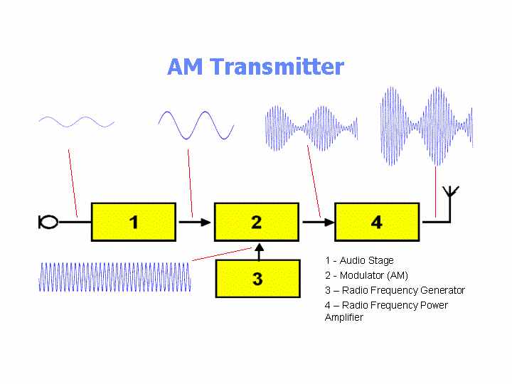
Block diagram of radio. Receivers - Block Diagram - Electronics Circuit and Tutorials - Hobby Science Projects - Most of these blocks are discussed individually and in more detail on other pages. Audio Stage Amplifies increases the weak signal coming from the microphone.
Antena penerima Receiving Antena. Berfungsi sebagai penangkap getaransinyal yang membawa dan berisikan informasi yang dipancarkan oleh pemancar. Berfungsi mencampurkan getaransinyal RF.
Each block in the diagram has an underlying mathematical model. GENERAL COMMENTS The main objective of these diagrams is to help students understand the operation of transmitters and receivers of various types by showing how the signal changes as it propagates through each stage in a series. Diagram Blok Radio Penerima AM Superheterodyne.
Block diagram of radio In order to better understand the way the radio transmitter works block - diagram of a simple AM amplitude modulated signal transmitter is shown on Pic. Most of the diagrams date back to the late 1980s or early 1990s. Diagram Blok Radio Penerima AM Superheterodyne.
In low-level modulation the powers of the two input signals of the modulator stage are not amplified. Receiver Tutorial Circuits - AM. In high-level transmission the powers of the carrier and modulating signals are amplified before applying them to the modulator stage as shown in figure a.
Skema blok pemancar AM memiliki empat bagian utama yang dapat digambarkan sebagai blok. Diagrams and each of these comments is inserted in the main text adjacent to the diagram that it explains. F - f m f c MIXER IF LOCAL OSCILLATOR AMPL DEMOD DETEKTOR f c RF AMPL f LO AUDIO AMPL f.
Figure a shows the block diagram of high-level AM transmitter. VII4 BLOK DIAGRAM PENERIMA AM FM c GbrVII-3 Blok diagram Penerima Radio a. The AM superheterodyne radio works by a transmitted signal which is picked up by the.
Modulation can be by varying the amplitude or height of the carrier known as amplitude modulation am or by slightly changing its frequency waveform known as Frequency. The working of a superheterodyne receiver is explained with the help of the block diagram given below in Fig along with the waveforms at the output of each block. Semua bagian blok mempunyai peran dan fungsi sendiri-sendiri namun tidak dapat terpisahkan satu sama lain.
Fungsi tiap bagian pada blok diagram radio penerima FM supereheterodyne diatas dapat diuraikan sebagai berikut. Pada blok diagram radio penerima FM di atas pembatasan ini berfungsi untuk mendapatkan nilai linear dari sinyal IF sebelum masuk ke Detektor yang sering berupa rangkaian Diskriminator fasa. Setelah diperkuat geteran RF dicatukan ke mixer.
AM and FM Transmitters. Penerima AM FM a. Proses pengembalian pesan asli dari bagian frekuensi pembawa ini dapat dinikmati setelah melalui beberapa tahapan proses pada tiap bagian blok diagram radio penerima FM.
Learn everything about AM Receiver. Sebagai penangkap getaransinyal yang membawa dan berisikan informasi yang dipancarkan oleh pemancar. Visualize the big picture of the AM radio transmitter receiver and interfering signals with a system block diagram.
Fungsi Blok Radio AM dan FM Pemancar FM. Diagram Blok Pesawat Penerima AM Pesawat penerima radio yang dipelajari sekarang adalah suatu penerima dengan sistem amplitudo modulasi AM yang mempunyai daerah frekuensi 520 kHz 1630 kHz 577 184 meter yang disebut daerah gelombang menengah medium wave band MW. Fungsi Blok Penerima AM Antena.
Start with the AM signal model The signal model for an AM signal is where Ac is the carrier amplitude fc is the carrier frequency mt is. Berfungsi untuk menguatkan daya RF Radio Frequency Frekuensi tinggi yang berisi informasi sebagai hasil modulasi pemancar asal. The amplitude modulation is being performed in a stage called the modulator.
Berfungsi menangkap gelombang elektromagnetik termodulasi yang bersal dari antena pemancar radio. The schematic and BOM show a 200µH inductor and a trimmer capacitor 150-500pF though these parts can be salvaged from an old AM radio to preserve the directional nature of a tuning coil and an adjustment knob plate capacitor that work well for radio reception. Modulator The audio or data signal is modulated onto the radio frequency carrier in this modulator stage.
Antenna processed through the set to the speaker as follows. Blok diagram rangkaian pemancar radio AM. Gambar Blok Diagram Pesawat penerima AM.
Demodulator sebagai bentuk dasar penerima b. Yaitu blok power supply blok modulator blok osilator dan penguat RF yang terakhir adalah blok antena. Penguat tala IF dan Pembatas Penguat Tala IF membentuk sebuah rangkaian BPF dengan Band Width 150 kHz pada nilai tengah 107 MHz.
Sebagai penangkap getaransinyal yang membawa dan berisikan informasi yang dipancarkan oleh pemancar. Fungsi dari masing masing Blok dan prinsip kerjanya a. Sekian pembahasan tentang Blok Dagram Pesawat Penerima Radio AM dan FM semoga dapat bermanfaat dan mudah dipahami.
 12v 60a Car Battery Maybe Dead Battery Charger Circuit Battery Charger Battery
 Testbeelden Van De Nederlandse Televisie Testbeeld Televisie Bane
 Cheap Hot Air Station With Arduino Hot Air Arduino Station
 Simple Fm Radio Sure Works Fm Radio Radio Electronic Schematics
 Samsung Lcd Tv Circuit Schematic Circuit Diagram Tv Services Lcd Tv
 Block Diagram Of Am Modulation Circuit Design Amplitude Modulation Circuit
 Pin On Basement
![]() Am Transmitters
Am Transmitters
 6 Transistor Vhf Super Regenerative Receiver Electrical Engineering Books Shortwave Radio Radio Design
Posting Komentar untuk "Diagram Blok Radio Am"